The case study featured here is a 3 MW doubly fed induction motor (DFIM) drive used for mining applications. The DFIM drive controls were designed, built, and tested by Indrivetec AG, at the request of CSE-Uniserve. Indrivetec AG is a Zurich-based power electronics, drives, and energy storage company and is an early adopter of Hardware-in-the-Loop (HIL) technology with a research lab primarily based on HIL for control design and testing.
The stator of this motor is connected to the medium voltage grid, and the rotor is connected to a liquid resistor of the system integrator CSE-Uniserve and an Indrivetec Insulated-gate bipolar transistor (IGBT) converter. Here, the resistor is used for starting and running at a constant speed, while the converter is used for variable speed operation.
What are major challenges of designing and testing motor drive controls in general?
Industrial drives are often complex systems with several components from different vendors that need to be integrated. When commissioning such systems, it is important to avoid surprises on-site and test all key functionalities before commissioning, such as drive control, process control, fault scenarios, protective functions, control tuning, and robustness.
Complexity and Risk
For drives with induction machines, grid faults are one of the major challenges because the motor is directly coupled with the grid. The motor drive controls need to be designed and tested for optimal performance in various fault scenarios, such as thermal losses, switching delays, and low-voltage ride through (LVRT). It can also be demanding for converter manufacturers to develop and validate complex control functionalities, including process control, protective functions, control tuning, and robustness.
Accurate Models for Thermal and Switching Loss Calculation
Among the biggest challenges for motor drives is designing and testing the adequate cooling system. There is only one way to prevent semiconductor overload: loads and thermal losses need to be well shared among all semiconductors within the system. This requires the use of precise models for thermal loss calculation. Cost-effective design is then achieved by properly sharing the load of the thermal losses in semiconductors and by building the correct cooling system for the whole converter.
Simulating Grid Faults
Recreating test scenarios with real equipment and power hardware can potentially have destructive effects. Transient currents, for example, are multiple times the rated current of the motor. This means that during the design process, you must find and limit the stress on power semiconductors and protection circuits which is used to dissipate energy when the machine slows or shuts down. After the design, you need to test the components accordingly, and verify protection mechanisms.
Meeting Customer Demands
While customer acceptance tests cover the basic functionality testing, standards compliance tests are more complex, as they are specific to the customer and local market demands. These tests are done to ensure product quality and guarantee reliable operation in the customers’ environment. Such testing is very demanding due to a high variability in environments in different countries.
What are the advantages of using Model-Based System Engineering (MBSE) and Hardware-in-the-Loop (HIL) for designing and testing converter controls?
Reduce Risk of Damaging Converter Hardware
Using HIL, you can emulate the power stage in real time, so the converter controller behaves as if it were connected to real hardware, as it cannot distinguish between the emulated power stage and the actual power stage. This allows you to quickly and thoroughly test software in as many scenarios as possible without risk, even fault-dependent cases.
Vertically Integrated Testing Environment
Testing the validity of your design and product starting from the earliest steps of the life cycle prevents you from failing to notice potentially problematic product behaviors that otherwise wouldn’t be discovered until physical integration. These behaviors are easier to predict and optimize when addressed in early development.
The system life cycle usually consists of several phases, during which separate teams tackle the challenges at different complexity levels of the system from various aspects. By having an MBSE tool that can assist you throughout as many of these phases as possible, you can simplify and speed up communication between teams by employing a commonly used tool. or adapt them to different tools along the life cycle, avoiding the need for multiple costly tool licences. As a result, they also achieve their targets in less time with lower financial investments. Having a vertically integrated testing environment is a lifesaver for both engineers, integrators, and investors alike – because it can be accessible and understood by all.
Real-Time Parallel Simulations
The Typhoon HIL system architecture allows electrical and thermal models to be simulated in real-time and in parallel on two separate processors. This not only saves a lot of time, but also improves processor performance compared to running both models on one processor. Better performance in turn, enables the small time-steps demanded by highly dynamic power electronics applications. Moreover, increasing the complexity of the thermal model won’t affect the electrical model simulation performance and vice versa.
DFIM Motor Drive for mining application Case Study Example
Project Challenge
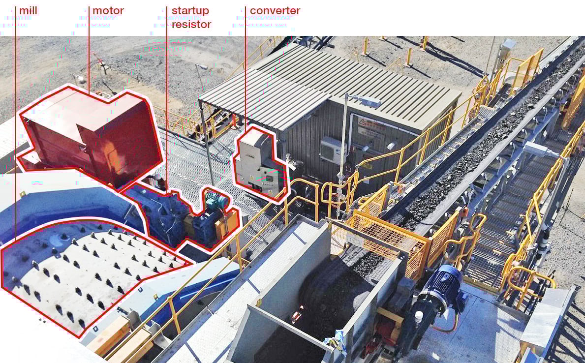
The key challenge for this case study is ensuring the seamless transition of the motor drive from running at constant speed to variable speed operation. Running at variable speed in this application optimizes the grinding efficiency depending on the amount and properties of the incoming material. However, the motor, startup resistor, mill, inverters, switch gear, process control are all from different suppliers and interact in a complex way, making untested variable speed operation risky. You can see the aerial view of the DFIM Drive Mining installation site in Fig. 1 below:
Figure 1. Aerial View of the DFIM Drives Mining installation site with Indrivetec AG Motor Drive.
Project Solution
A real-time Controller Hardware-in-the-Loop (C-HIL) simulation platform was crucial in addressing the design challenges in the case study. It enabled the design and test of control software off-site, proof of functionality before commissioning, dimensioning and testing of protective devices and their functionality, as well as the simulation of grid fault scenarios. You can see the HIL model setup used in this project Fig. 2.
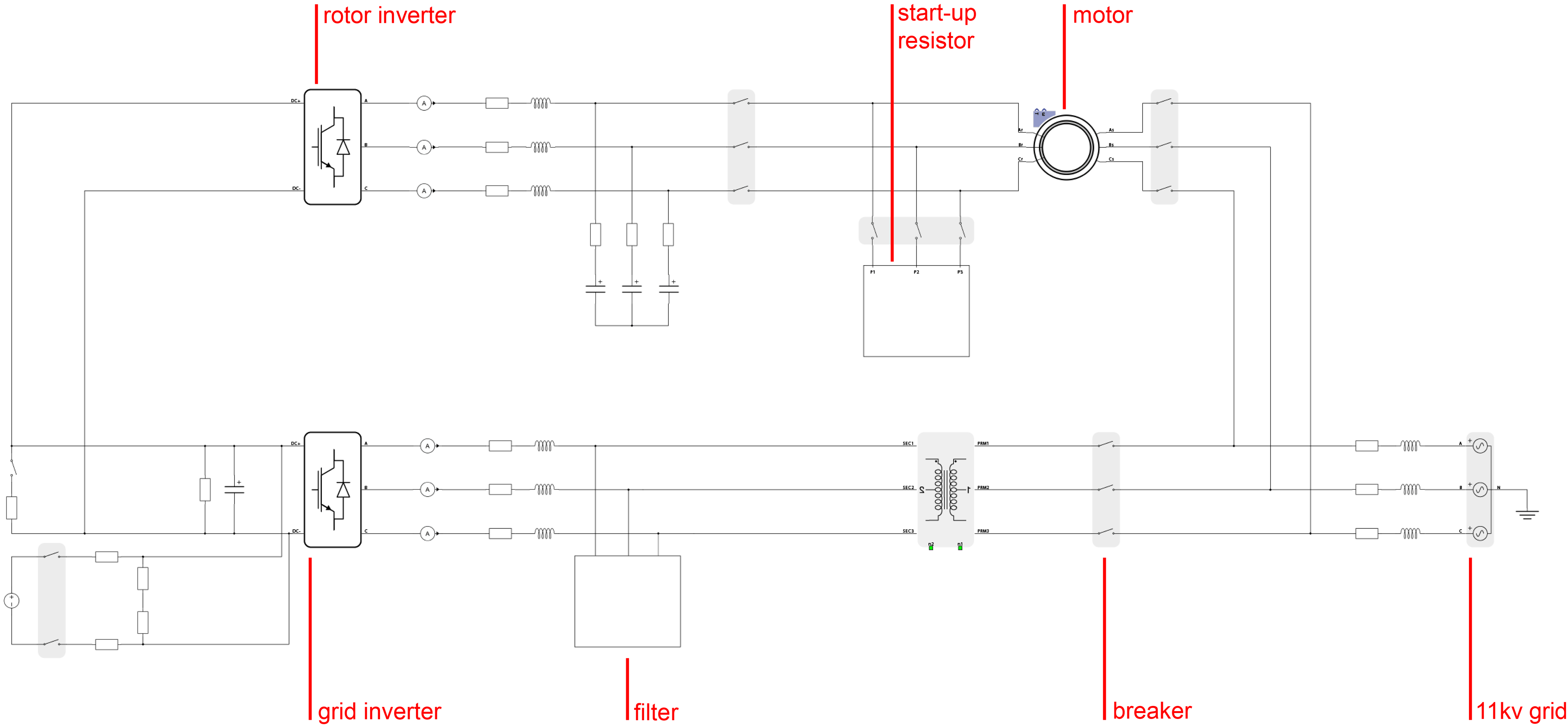
Figure 2. HIL Model of DFIM Motor Drive for Mining Applications.
Inverters and switches are driven by the real motor drive controller directly interfaced with the HIL402 real-time emulator device. Using real controls in the C-HIL stage results in higher fidelity model and more accurate measurements of controller behaviour in many scenarios that are difficult to recreate in the field. This includes over-stressing the components, over-current, over-voltage situations and their respective protection measures, as well as thermal stress.
All relevant operating modes and scenarios could be simulated in HIL SCADA, which allows you to monitor and interact with the simulations. For this application, a voltage sag on the grid side (low voltage ride-through) was implemented on HIL SCADA, that can be seen in Fig. 3.
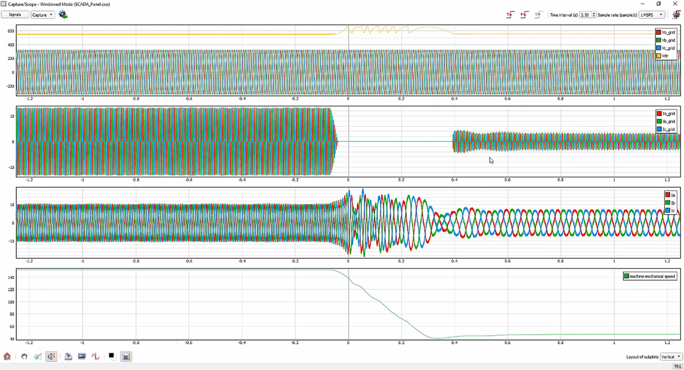
Figure 3. Real-time signals of grid voltage, machine current, and machine speed in HIL SCADA.
Case Study Summary
The advantages of HIL-based design and testing are that: it is highly flexible (change of parameters, components, configurations), scalable, it provides risk-free testing e.g. of overloads and design limits that could damage equipment, and it provides huge savings in time and infrastructure costs. The possibilities to perform real-time testing by connecting and using the real control software (C-HIL) is the major advantage of the HIL system over CPU-based computer devices, as you gain full insight into the real behavior of the control software. In other words, while simulation only approximates the behavior of control software, the C-HIL gives you a high-fidelity, real-time insight into the behavior of the actual control software.
Are you interested to adopt HIL in your work?

Are you interested in more stories like this?

Credits: This text is based on the interviews that are available in the webinar HIL for Variable Speed Drives, where the introduction was given by Christoph Schaub, the Sales Director of the DACH region at Typhoon HIL, while the use case was presented by Dr. Andreas Dittrich of Indrivetec AG.
