From Centralized to Distributed Microgrid
Today, most microgrids are controlled in a centralized fashion with standard master slave architecture. There is a central controller, which is the supervisory controller and is connected via point-to-point connection to every DER in the microgrid.
Researchers from the University of Illinois at Urbana Champaign (UIUC) funded by ARPA-E, have developed a completely distributed controller architecture. Instead of a central controller, multiple micro controllers or nodes communicate with its neighbors towards a consensus. Olaolu Ajala, a PhD student in power and energy systems at UIUC, shows how this distributed controller architecture works using a Hardware-in-the-Loop microgrid testbed.
Hardware-in-the-Loop Microgrid Testbed
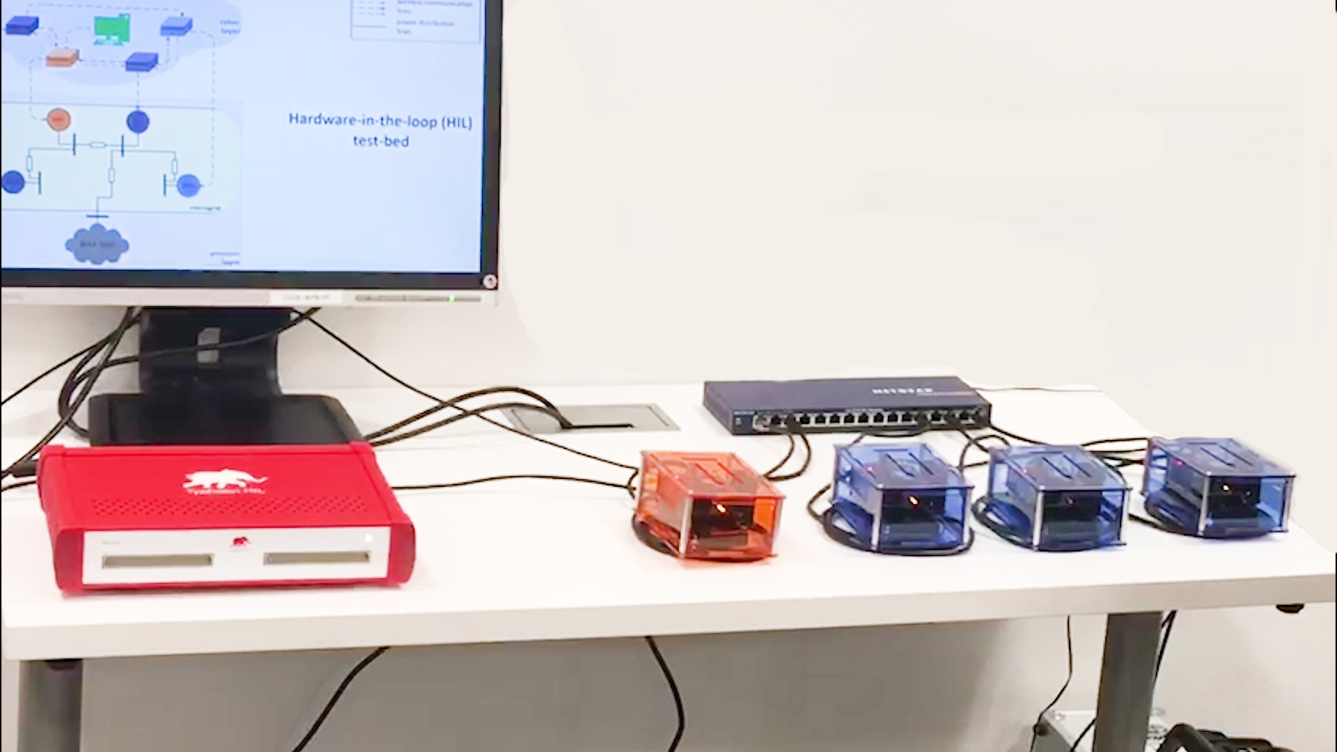
The distributed microgrid control demo comprises a Hardware-in-the-Loop testbed with multiple distributed controllers, one for each inverter used for the coordination of distributed energy resources (DER). The demo shows a frequency regulation service provided to the bulk grid as an example.
In this Hardware-in-the-Loop testbed, an independent system operator sends a regulation signal to the aggregator, represented by the computer, every 2-4 seconds. Using this information, the aggregator determines the required total change in generation for the tie-line interchange to track the regulation signal. The aggregator then communicates this change to the leader which is represented by the orange-colored micro-controller.
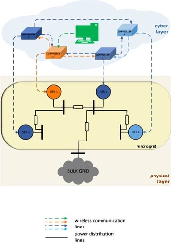
Two Microgrid Testbed Layers
The physical layer consists of a microgrid, interconnected to a bulk power grid through a set of tie-lines. The microgrid has 4 inverter-interfaced DERs, with each controlled to deliver specified real power and reactive power injections to the system. All is modeled and simulated on the Typhoon HIL402 real-time-simulator. The Typhoon HIL402 is used for high-fidelity modeling and real-time simulation of the physical layer.
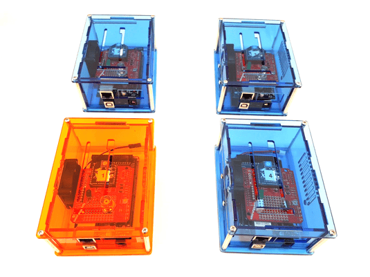
The cyber layer consists of an aggregator and 4 control devices interconnected over a communication network. Each control device in the cyber layer controls a DER in the physical layer. It is implemented in the hardware using these devices: a computer, 4 micro-controllers, and an Xbee-based wireless communication network.
The cyber layer performs three major tasks:
1) Determine the required change in total generation in the microgrid,
2) Distributively compute the optimal contribution of each DER to the required change in generation, and
3) Locally control each DER to change its generation accordingly.
Distributed Communication Network
A distributed communication and control architecture is implemented in the cyber layer. And at its core, the architecture is robust against communication link failures. Each of the 4 control devices are connected to a DER in the microgrid through Cat6 cables. And use the ModBus TCP communication protocol.
Immediately, the leader node communicates this information to its neighbors. They communicate to their neighbors and this process is repeated by all the control devices until the distributed system asymptotically reaches consensus.
Consensus is reached when all control devices have computed the optimal contribution of the DERs to the required change in total generation. As soon as consensus is reached, the control devices adjust the generation of the DERs they control accordingly.

