While computer aided design tools have found wide adoption by practicing engineers, control testing has been lagging.
Most of the control system type testing is still done manually, in the lab, using small scale or large full scale power hardware, which can significantly prolong the time it takes to bring new power electronics products to market.
So why do practicing engineers use power hardware to test their control systems in the first place?
One good reason is that until recently there was no satisfactory alternative. Once the real time software is loaded to the DSP and the FPGA starts generating PWM pulses with nanosecond resolution, there is little else what can be done other than hooking it up to their inverters and slowly increasing the voltage, hoping that this time they won't hear a loud BANG.
Luckily, things are improving and powerful, commercially available controller hardware-in-the-loop (C-HIL) test equipment are becoming available. VDC Research Group, a technology market research company, predicted in their report "The Global Market for Hardware-in-the-Loop Testing Solutions" that the adoption of commercial C-HIL solutions for power electronics will depend on the speed at which new C-HIL solutions will be able to replace the in-house developed test rigs industries have been building over the decades.
What is Hardware-in-the-Loop?
Hardware-in-the-loop means that there is something physical connected to the real-time simulation. This can be a piece of the power hardware or a piece of the controller hardware. HIL simulation with power hardware is often referred to as Power Hardware-in-the-Loop (P-HIL). In the case of HIL simulation where controller hardware is connected to the real-time simulation, it is called Controller Hardware-in-the-Loop (C-HIL).
Only recently, in large part thanks to the advances in FPGA technology, commercial C-HIL test systems with extremely small simulation time step and latency became feasible, and finally in 2009 the world’s fastest real-time digital simulator platform with 1 µs sampling time and latency became commercially available.
What is the difference between simulation and real-time simulation?
Real-time simulation progresses at the same rate as the actual time passes (the time you can observe on your wrist watch or your smart phone). The simulation time step can be anything, even minutes, so long as the simulation time corresponds to real time. This is in stark contrast to computer simulation that can be slower or faster than the real time.
What is this "C-HIL" and where did it come from?
C-HIL test method is the test procedure where the performance of the physical control system hardware, firmware and software is tested against a mathematical model, simulated in real-time on the C-HIL platform. This approach has been used for decades in automotive and aerospace industries as the method of choice when testing sophisticated control systems. By connecting controllers to the virtual plant model, simulated in real-time, they were able to test operating conditions that are difficult and/or impractical to test in the lab in addition to being time consuming and unjustifiably expensive.
Let us now look closer into some important benefits and trade-offs of C-HIL and the two related, yet distinctly different approaches: Software-in-the-Loop (SIL) and Power Hardware-in-the-Loop (P-HIL) methods of testing control systems.
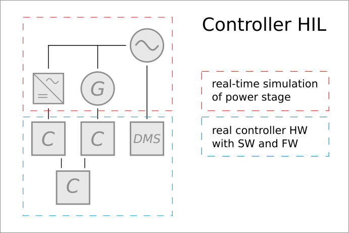
Controller Hardware-in-the-Loop (or "C-HIL") approach

With C-HIL, the real physical controller with all of its software and firmware is interfaced directly with a high-fidelity power stage model running in real-time within the C-HIL device. The primary purpose of the C-HIL approach is to test and validate the controller hardware, firmware and software through all possible operating conditions including the transient and most importantly fault conditions in both power and control hardware.
Benefits:
- There are no assumptions regarding the accuracy of control system models because the control system is real.
- Unlimited range of test operation points.
- Automatic and repeatable testing.
Challenges:
- Requires actual controller hardware.
- Signal conditioning interface may be required between between C-HIL device and control system under test.
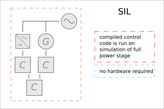
Software-in-the-Loop (or "SIL") approach

This method is commonly used for teaching. It is a hybrid of a DSP debugging tool and a power hardware simulator. An attractive feature of SIL is that it is usually not much more expensive than the simulation software itself (and the prices of software have been steadily reducing).
With advancements in automatic code generation, the debugging feature is losing significance. However with increasing speeds in simulation, SIL is trying to compete with the C-HIL approach but its speed is still limited due to the FPGA portion of the controller code.
All things considered this approach may be feasible for applications where the controllers are very simple (for ex. digital control in DC/DC converters) and in academia because of the low cost.
Benefits:
- Low cost
- Does not require controller hardware
Challenges:
- Questionable accuracy of control system modeling for anything but the simplest control systems
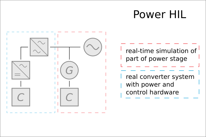
Power Hardware-in-the-Loop (or "P-HIL") system

This method is perhaps the most flexible and versatile method to test the whole power electronics converter system comprising the power hardware and control hardware. P-HIL can significantly reduce the complexity and increase flexibility of unavoidable full system tests.
Its usefulness for power electronics control system testing alone is questionable mainly because of the real power involved (which is mostly not relevant from the control system point of view) and the limited bandwidth of the systems, particularly when emulating potentially catastrophic faults such as short circuits.
Benefits:
- Simple interface: three power wires for 3-phase AC systems or two power wires for DC systems.
Challenges:
- Testing control system with power is potentially dangerous and costly.
- Insufficient bandwidth for all but a combination of slow dynamics controller under test and very high dynamics P-HIL system.
The Future of Testing
What is the future of power electronics controller testing tools?
Tighter integration of HIL testing tools with computer aided design tools, streamlining the product development process by better bridging the gap between the design and test stages of controller development, seems to be a logical evolutionary path that will benefit the end users the most as well as consolidate the industry.
This post was originally published in May 2016 and has been updated for comprehensiveness and accuracy.
---
Considering adopting a Hardware-in-the-Loop system for your power electronics laboratory? Check out what we have learned from working with our partners at the block below:

