
Have you ever wondered how engineers test and perfect the control systems behind photovoltaic inverters? This blog article, written by the Chief Technology Officer at Fimer S.p.A. dives into the world of Hardware-in-the-Loop (HIL) systems, a powerful tool that creates a safe and controlled environment to simulate real-world scenarios for inverter control boards. HIL systems not only accelerate development cycles but also ensure the robustness and reliability of these critical components. Read the blog article below to learn how HIL systems are used to test everything from normal operations to extreme grid conditions, ultimately contributing to the success of the final product.
For many years now, simulation has been a fundamental aspect of our control board design work used in inverters at Fimer. One of the first steps that significantly improved the development, debugging, and testing phase was undoubtedly the introduction of Hardware-in-the-Loop (HIL) systems.
A HIL system is a widely used simulation and testing technology in the fields of electrical engineering, electronics, and automation. This approach involves integrating real components, such as sensors, actuators, and controllers, with a virtual mathematical model of the system. This allows for simulating the entire system behavior within a controlled and reproducible environment.
The use of HIL systems enables real-time simulation, allowing for testing the operation of control boards by running embedded code without the need for a complete hardware system of the controlled plant. This enables testing abnormal or error situations, which could potentially cause hardware damage if the development code does not align with the required specifications.
A C-HIL (or Controller-HIL) simulation includes the emulation of sensors and actuators (current probes, switches, relays, IGBTs, etc.). These emulations serve as an interface between the plant simulation and the embedded system under test. The value of each electrically emulated sensor is controlled by the plant simulation and read by the system under test (feedback). Similarly, the system under test implements its control algorithms by sending actuator control signals. Changes in the control signals result in changes to variable values in the plant simulation, leading to changes in feedback.
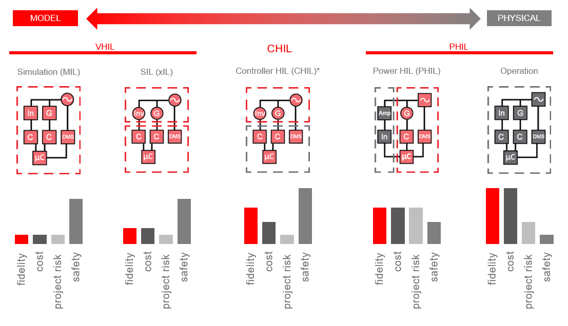
Figure 1. From Virtual HIL to Power HIL.
For many years, our choice has fallen on Typhoon HIL systems, which offer a good combination of computing power, ease of use, the number of I/O, and flexibility. Typhoon HIL simulators are based on a heterogeneous multiprocessor architecture, including FPGA, system CPU, and user CPU, enabling accurate and complete system simulation.
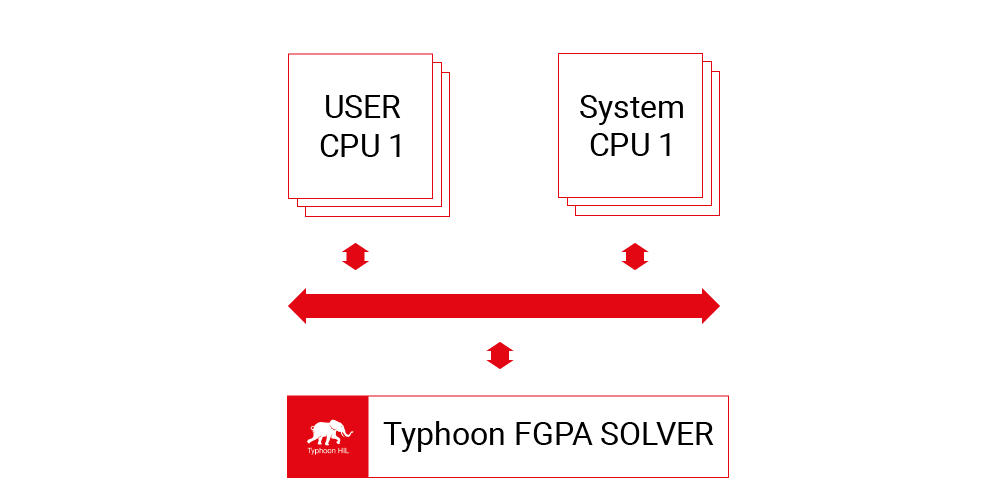
Figure 2. Typhoon HIL simulator architecture.
The integration of photovoltaic inverter control logic with HIL systems has become an integral and deeply rooted part of our company's DNA. From the early stages of developing a new product, we define the corresponding HIL interface, designing a controller-HIL interface board to achieve a setup that allows analyzing the behavior of control boards and verifying the maximum number of functionalities.
To analyze the behavior of control boards and verify the maximum number of functionalities, the optimal choice is to design an interface board between the controller and the HIL system. This process takes place from the early project stages, in parallel with the definition of the controller itself. The interface board must be carefully designed to enable a complete system simulation, going beyond providing analog feedback to the inverter or receiving PWM signals. It must also accommodate additional elements such as relay commands, meters, chargers (in the case of Energy Storage Systems or ESS), and other relevant components.
A crucial aspect in setting up the system is the scaling and assignment of analog signals output from the HIL, which constitute feedback for the control board. The quality of feedback is essential to ensure accurate and reliable simulation of the system. To achieve the best quality of feedback, two main elements can be considered:
- Scaling of signals output from the HIL: It is important to correctly calibrate the analog signals generated by the HIL to be compatible with the system and inverter requirements. This scaling may include adjusting voltage levels, current, or other quantities to match the specifications of the real system.
- Scaling of signals on the HIL<->Logic interface board: Equally crucial is adapting the input signals to the control board to ensure proper controller operation (e.g., voltage levels for PWM control). This may involve transforming signals to meet voltage, current, or other requirements specified by the control board.
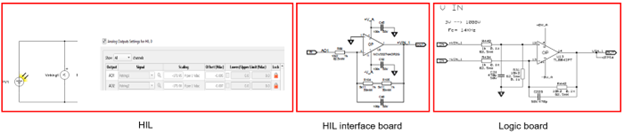 Figure 3. Analog signal interface example, from HIL to control logic board.
The following image shows a typical setup of an Energy Storage System (ESS); the system uses an HIL604 and is capable of simulating a 3-phase inverter connected to up to 3 independent battery packs.
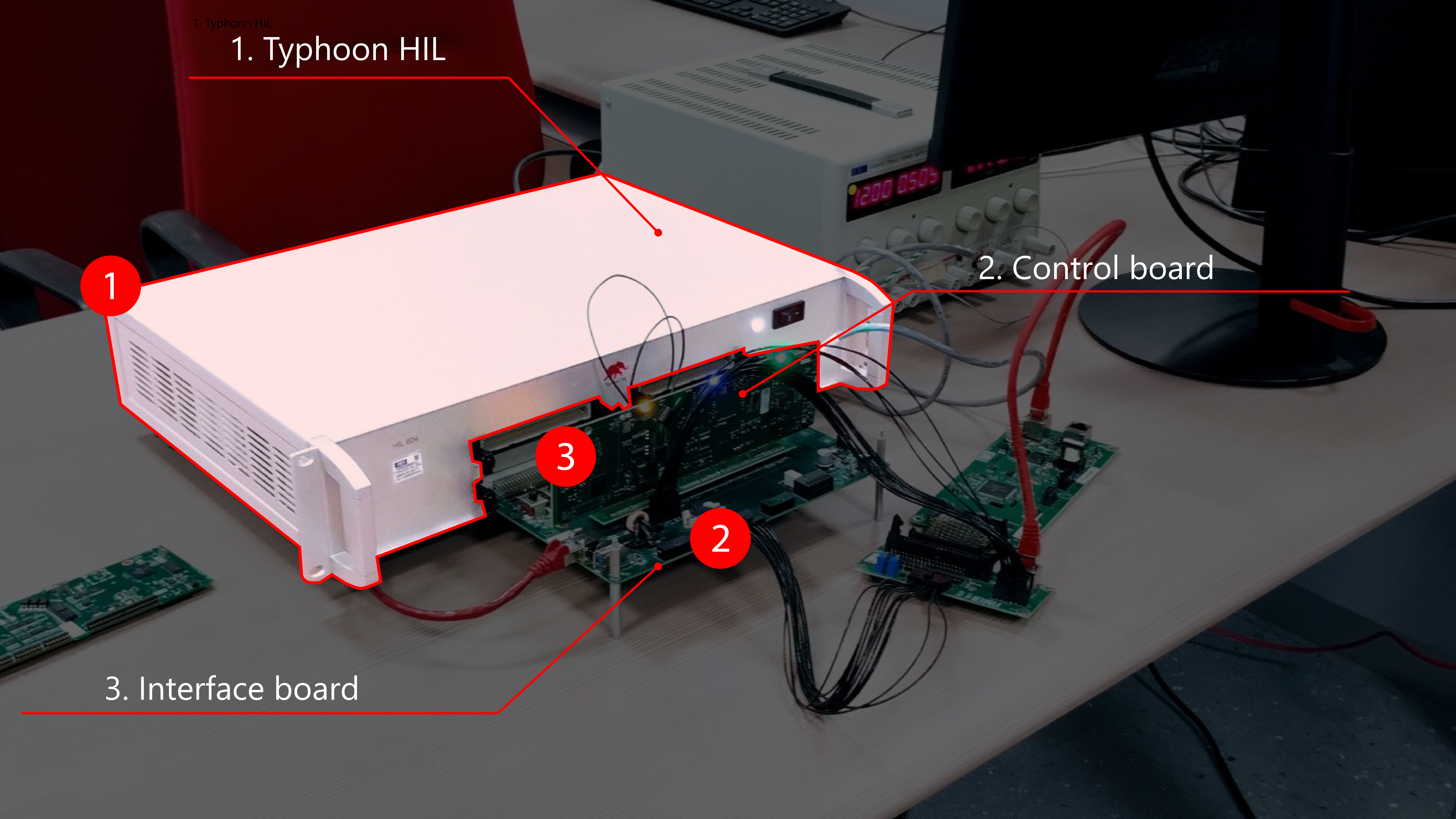
Figure 4. ESS system HIL604 setup; 3-ph inverter plus battery charger.
The next image shows another inverter setup, this time implemented with an HIL602.
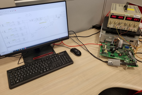 Figure 5. 3-ph Inverter HIL602 Setup.
The advantage of this approach is evident:
- Controlled testing environment: With an HIL system, it is possible to create a controlled and reproducible testing environment for the control board. This simulated environment allows tests to be conducted under various conditions and scenarios, including abnormal or error situations, to verify code behavior in real-world conditions.
- Safety and cost savings: Using a HIL system eliminates the need to connect embedded code to a real system, reducing the risks of hardware damage during development. Additionally, it avoids the consumption of physical resources and potential wear and tear on real actuators or sensors during testing, contributing to significant cost savings.
- Development speed: The ability to conduct tests in a virtual environment allows for a faster development cycle. Tests can be performed more efficiently and effectively, reducing the time required to complete the project.
- Verification of complex functionalities: An HIL system allows testing complex functionalities and interactions between various components of the control board. It can verify whether embedded code works correctly when involved in different operations or interacts with other parts of the system.
- Early detection of errors: HIL simulation helps identify coding errors and issues during the development phase. This enables timely corrections and improvements, reducing the risk of costly and challenging-to-resolve bugs in later development stages.
- Testing extreme cases and critical situations: An HIL system enables testing extreme scenarios or critical situations that may be difficult or dangerous to replicate in the real world. This ensures that embedded code is robust and responsive even under challenging conditions.
- Test repeatability: The virtual nature of HIL systems allows tests to be repeated consistently and reliably. This is crucial for ensuring result reproducibility and continuous verification of code changes.
Points 2 and 6 can be well represented by real situations encountered in the development and verification phases of our systems, particularly for high-low voltage ride-through (HLVRT) and anti-islanding (AI) tests.
 Figure 6. Inductive 90 kVA LVRT equipment implemented on dedicated 690 Vac line.
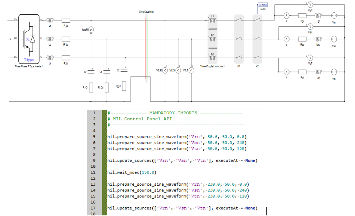
Figure 7. HLVRT implemented by HIL Simulation and Python Script.
An HLVRT test on a medium/large-sized inverter (several tens/hundreds of kW) requires expensive and bulky equipment that demands significant investments in terms of infrastructure and human resources. These tests must be conducted on the machine to demonstrate compliance with regulatory requirements. However, using these setups during the development phase is complicated and requires the collaboration of multiple people and a considerable amount of time.
Using HIL systems in this design phase immediately simplifies the process, as it only requires a simple model enriched with a few lines of script (Fig. 7) using the APIs provided by the tool, which easily automate the execution of any fault condition, defining its magnitude and duration.
Another example is anti-islanding tests; setting up test environments in this case can also require significant investments (Fig. 8).
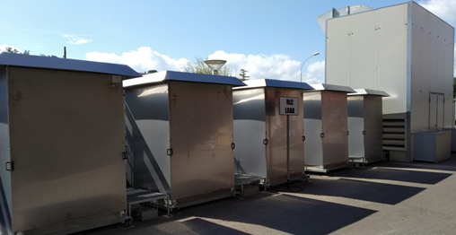 Figure 8. 250 kVA R-L-C Passive Load with 400 Vac nominal voltage.
Preliminary verification, on the other hand, can be performed "on the bench" simply by modifying the HIL model and inserting the resonant loads (Fig. 9).
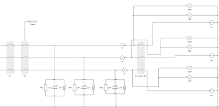 Figure 9. Anti-Islanding HIL Simulation Model.
In conclusion, the use of HIL systems has proven to significantly simplify and improve the development and verification process of control boards for photovoltaic inverters. It enables faster, safer, and more reliable design, providing a solid foundation for the success of the final product.
Are you interested to learn more about Fimer?

Are you exploring adopting HIL in your work?

Are you interested in more stories like this?

Credits
Author | Giovanni Manchia, Chief Technology Officer at FIMER S.p.A.
Visuals | FIMER S.p.A.
Editor | Debora Santo
This blog article was originally published as a LinkedIn article by Giovanni Manchia, Chief Technology Officer at Fimer S.p.A., available here and it is being republished with the author's permission on Typhoon HIL blog.
