
Interconnecting distributed energy resources (DER) to the grid, in the United States, requires compliance with a number of standards/grid codes, where three main ones are:
- National Electrical Code (NEC),
- Underwriters Laboratories (UL) 1741, and
- IEEE 1547.
Since the existing versions of UL 1741 and IEEE 1547 (IEEE 1547-2003) were written prior to the development of smart inverters they were being revised in the end of 2016 to cover new grid support, utility-interactive inverters and converters. Revisions of UL1741 and IEEE 1547 came from California. Indeed, in early 2013 regulators at the California Public Utilities Commission (CPUC) and California Energy Commission (CEC) jointly convened the Smart Inverter Working Group (SIWG).
The CPUC approved the Phase 1 recommendations of the SIWG to require the 7 additional autonomous functions under the Rule 21, on December 18, 2014. Under the CPUC’s ruling, the effective date for these changes was set as the later of either December 31, 2015, or 12 months after UL 1741 is updated to accommodate SIWG’s Phase 1 recommendations.
In the end of 2016, UL officially published the updated UL1741 SA document, and with that the race began, to pass all the tests and certify our inverters before the one year mark expires.
Now, many manufacturers are still working on implementing the new standard. If you are still not sure what it includes, please read on.
UL1741 SA covers the compliance of grid interactive features, that are not covered in IEEE 1547, including but not limited to:
- Voltage ride through (L/HVRT);
- Frequency ride through (L/HFRT);
- Fixed power factor (SPF)
- Volt-VAr control (VV)
- Normal ramp rate (RR)
- Soft Start Ramp Rate (SS);
- Anti-islanding testing with
- Optional: Frequency-Watt (FW)
Anti-islanding testing is included in UL1741 SA since grid support functions might have an impact on inverter’s anti-islanding functionality. Hence, anti-islanding testing will need to be performed with these functions enabled.
Here is a brief description of 7 key tests that a grid support utility-interactive inverter needs to pass.
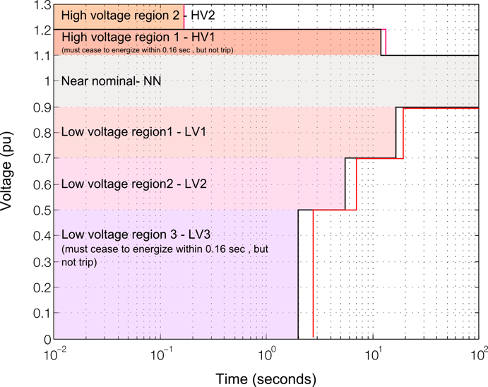
1. Low/high voltage ride-through (L/HVRT) test
The purpose of this test is to verify the behavior of the distributed energy resource (DER) in response to low and high voltage excursions that are outside the normal range of operation.
There are three types of inverter responses and six voltage regions, outside the near nominal operating regime, that need to be verified, namely: mandatory operation, momentary cessation (also referred to as gate blocking), and must trip. Operating regions are shown in the figure below.
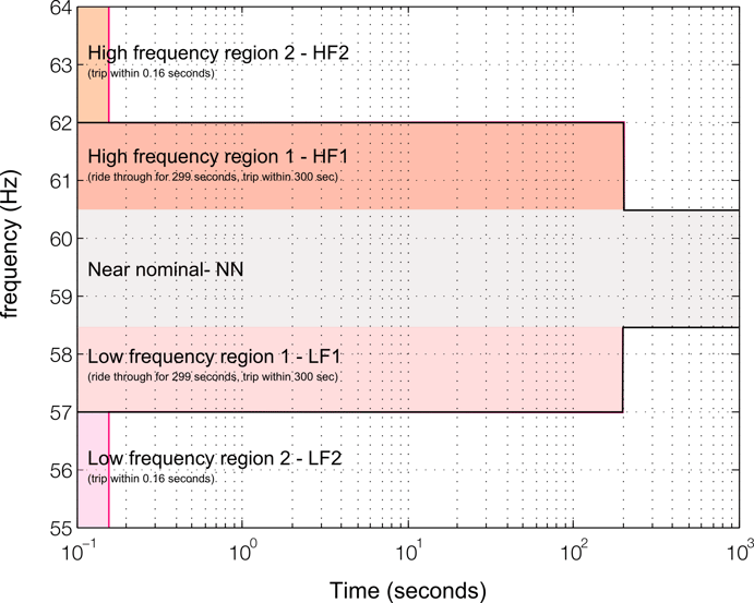
2. Low/high-frequency ride-through (L/HFRT)
The purpose of this test is to verify the behavior of the distributed energy resource (DER) system in response to low and high-frequency excursions which are outside the normal range of operation of the grid the inverter is connected to.
Similarly to L/HVRT, in frequency ride through there are three types of inverter responses and five frequency regions, including near nominal operating regime, that need to be verified, namely: mandatory operation, momentary cessation (also referred to as gate blocking), and must trip. Operating regions are shown in the figure below.
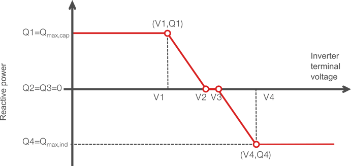
3. Volt/VAr “Q(V)” test (VV)
This test confirms that an inverter meets the required response characteristics for providing reactive power as a function of the grid voltage.
This test is defined in 4 voltage operating points along one Q(V) curve, and the inverter is checked for the reactive power it injects. A typical Q(V) curve that needs to be met is given in the figure below. The reactive power response is typically checked for three sets of Volt-VAr curves, namely average Volt-VAr, most aggressive Volt-VAr, and the least aggressive Volt-VAr.
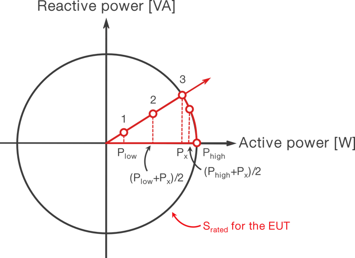
4. Fixed power factor test (SPF)
This test confirms that an inverter meets the required response characteristics for providing reactive power in response to a power factor command. Fixed power factor tests whether an inverter can maintain constant power factor for different active power levels.
When an inverter is in fixed power factor mode and it reaches the apparent power limit it will reduce active power in order to maintain fixed power factor.
If the inverter is in fixed power mode with reactive power priority, and it reaches the apparent power limit it needs to reduce the active power factor in order to maintain reactive power output.
A typical W-VAr graph with key operating points against which the inverter output is checked is given in the figure below.
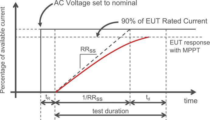
5. Soft-start reconnection ramp rate
This test checks whether an inverter meets a given response characteristic for providing ramp rate responses for soft-start.
DER’s can change the rate at which they increase and/or decrease their power output. These ramp rates are constrained by what the current level in the inverter can physically do. For instance, if they are outputting their maximum power, they can ramp down but cannot ramp up, while a completely charged storage system may discharge power into the grid but cannot draw power from the grid as it is already completely charged.
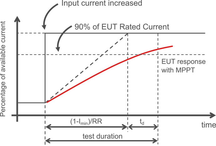
6. Ramp rate limitation test (RR)
This test checks whether an inverter has correct ramp rate responses for both normal ramp-up and ramp-down rate commands.
7. Unintentional islanding test
The unintentional islanding test is geared toward unintentional islanding evaluation when the support functions are enabled. This test is different from IEEE 1547.1-2005 since it includes grid interactive functions such as LVRT, HVRT, Q(V), Volt-VAr etc.
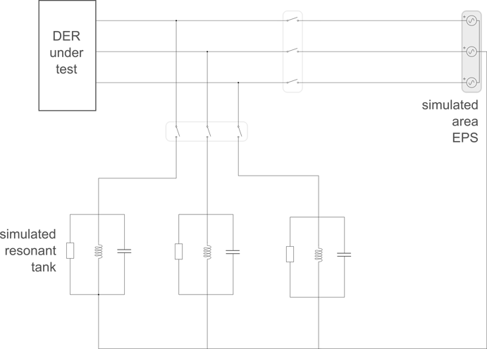
The unintentional islanding test is typically done in a test setup shown in the figure below. It is done in such a way that RLC network impedance is tuned until all the inverter current is going into the RLC tank and none goes into the three-phase source. At that moment, the three-phase source is disconnected and the inverter under test needs to rapidly detect the unintentional islanding connection and rapidly disconnect.
This test is repeated for different levels of the RLC network detuning from the zero current condition.
For the unintentional islanding tests, all the grid support functions must be activated with the worst-case parameters. If the DER under test includes a Frequency-Watt function, it must be tested as well. Test number one must include: L/HVRT, L/FVRT, (FW if available). Test number two must include: L/HVRT, L/FVRT, SPF, (FW if available). Test number three must include: L/HVRT, L/FVRT, VV, (FW if available).
Although these 7 smart inverter tests don’t impose any radically new requirements on smart inverter controllers, they require an incredibly broad spectrum of test cases that need to be covered.
Considering the number of test cases and the fact that all of these tests target inverter controller functionality, UL1741 SA testing and pre-certification lends itself perfectly to Hardware in the Loop testing (as well as other smart inverter grid codes such as BDEW etc.). Watch on demand and view automatically generated test reports for BDEW pre-certification.
Indeed, all the tests can be implemented and testing can be automated with a ultra-high fidelity controller hardware in the loop setup where the inverter controller can comprehensively be tested and validated without the need for high power lab testing.