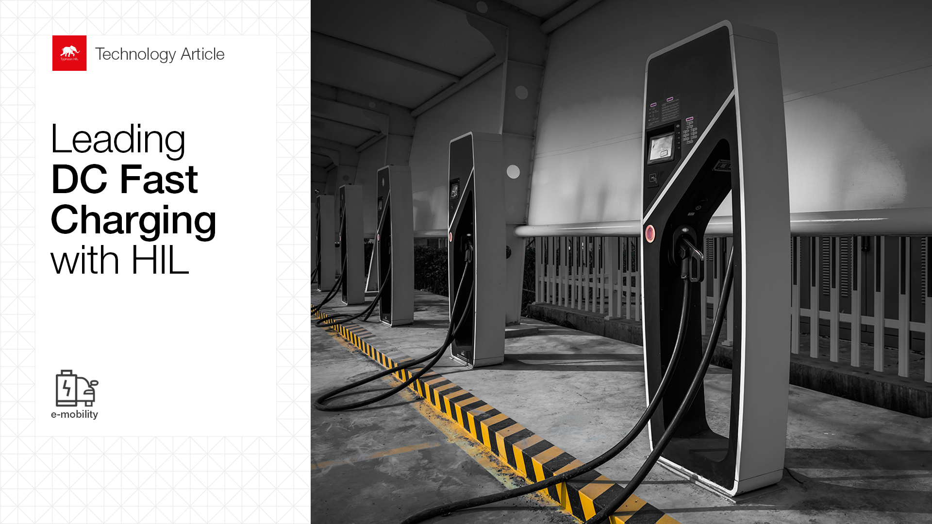
Introduction | Why are DC fast chargers important?
With governments tightening regulations for CO2 emissions, the e-Mobility industry has been considered a critical piece for driving the world towards a low-carbon future and reducing our dependency on fossil fuels.
In the last few years, AC charging has contributed positively to increasing the popularity of EVs. However, to achieve their mass adoption, charging time needs to be drastically reduced, bringing the charging experience closer to the fueling time of conventional vehicles. In addition, fast charging stations should become widely available around the globe to enable long-distance driving.
The necessity of speeding up charging and providing higher power densities to electrify large fleets has made DCFC vital for achieving carbon neutrality. These chargers will enable EV owners to charge their vehicles in minutes by providing DC power directly from the fast-charging station. However, these advantages that DC chargers bring to the widespread adoption of e-Mobility come along with several challenges.
DCFC Architectures | The status-quo of power electronics for DC fast charging
While Level 2 chargers (AC chargers) operate anywhere from 3 kW to 22 kW, Level 3 chargers (DCFC) operate at much higher power levels, delivering from 50 kW up to 350 kW, or even more. This increase in charging power has required that the manufacturers provide an alternative path to charging the vehicle through an off-board charger that would provide DC power directly to the battery, bypassing the on-board charger and not affecting the size and weight of the EV. To achieve high-power densities, DCFCs take advantage of the three-phase electrical service, typically ranging from 400 V to 480 V, and operate at higher currents than AC chargers, meaning they are more expensive in terms of development, installation, and usage.
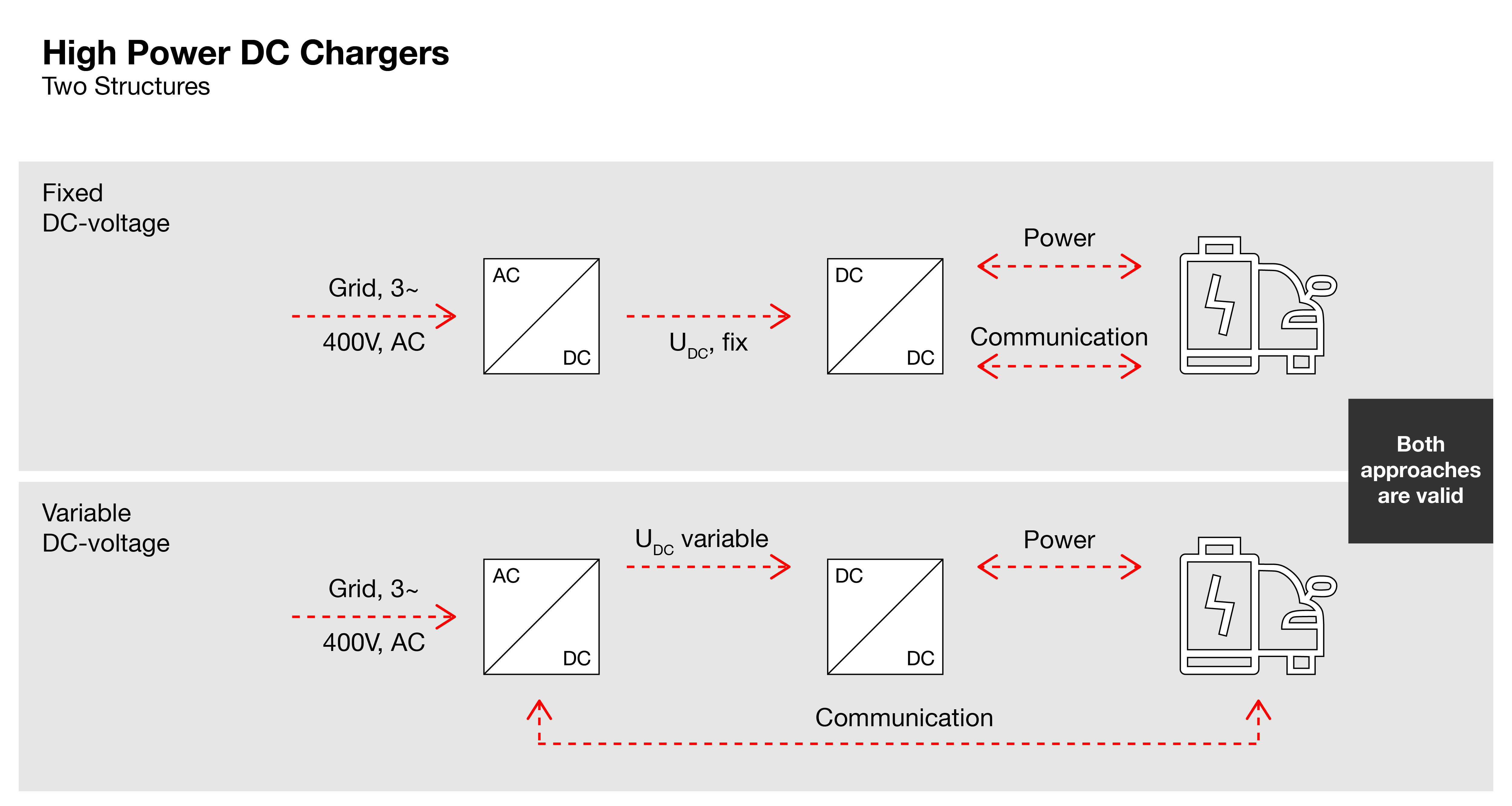
Currently, two fundamental methods are commonly used in high-power DC charger design, as shown in Figure 1. In the first method, a charger controller communicates with the EV and provides a control signal to a rectifier so that it produces a variable DC output voltage based on the car’s demand. Then, a DC-DC converter links the variable DC voltage bus to the battery. In the second approach, the input AC voltage is converted into a fixed DC voltage, and the DC-DC converter receives the control signal from the charge controller to control the output DC voltage to suit the requirements of the car.
In both methods, the AC-DC stage is usually employed for Power Factor Correction (PFC), responsible for ensuring a high-power factor operation to meet grid harmonic injection standards, while the DC-DC converter controls the charging voltage of the battery.
Challenges | Key challenges in testing controllers for DCFC power converters
Although the power conversion stages in DC chargers haven’t changed from the AC charging approach, single-phase rectifiers used in on-board chargers are now replaced with three-phase rectifiers to process more power, such as the Vienna rectifier, which demands more components and more complexity in the control system. In the DC-DC stage, resonant, soft-switching converters, such as the CLLLC Resonant Dual Active Bridge topology, have improved reliability, efficiency, and energy density. Still, these advantages come with the increased complexity of the control systems.
When validating controllers for DCFC with physical prototypes, the testing process involves many safety risks. These power converters operate at high power levels and are tested under extreme conditions, including grid faults, current/voltage spikes, overcurrent/overvoltage conditions, and faults occurring on the EV or charging station. These conditions are hard to recreate in the laboratory and can increase the development costs if damage to physical power electronics occurs.
In addition, new market trends impose modifications to the DCFC converters and controllers. An example is a popular new concept called Vehicle-to-Grid (V2G), which enables the EV battery to send power into the grid. However, its implementation requires a bidirectional power flow capability of power converters, increasing control and hardware complexity.
HIL-Based DCFC | How Typhoon HIL empowers the development of Level 3 chargers
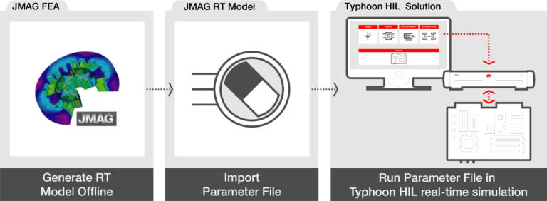
Hardware-in-the-loop (HIL) devices enable you to build high-fidelity simulations and test all the components of an electrified powertrain, such as batteries, electric motors, power electronics, and intelligent charging systems. By taking advantage of test-driven model-based design, you can evaluate DC fast chargers earlier in the design cycle, improve project schedule performance, reduce the number of software bugs, enable teams to be more productive, and increase test coverage.
The Typhoon HIL all-in-one solution was tailor-built for testing power electronics controllers and communication systems for e-Mobility applications. Based on ultra-high-fidelity models available in the component library, the solution is robust and extremely effective in testing industry-grade controllers — yet allows flexibility to import models built on third-party tools, such as Matlab and Simulink. It enables you to quickly build a digital twin of the DC fast charging station and test the controllers and communication systems before even building a real prototype.
With HIL, you can perform tests for numerous scenarios and evaluate how the real system might react to unforeseen conditions and how your control system should react in each case. It is especially helpful for detecting and preventing grid faults, voltage oscillations, overcurrent, and more.
Using the Typhoon HIL Control Center model library, for example, you could build the AC-DC stage of a DCFC utilizing the block diagram of the Vienna Rectifier. The electric circuit of this rectifier is shown in Figure 2.
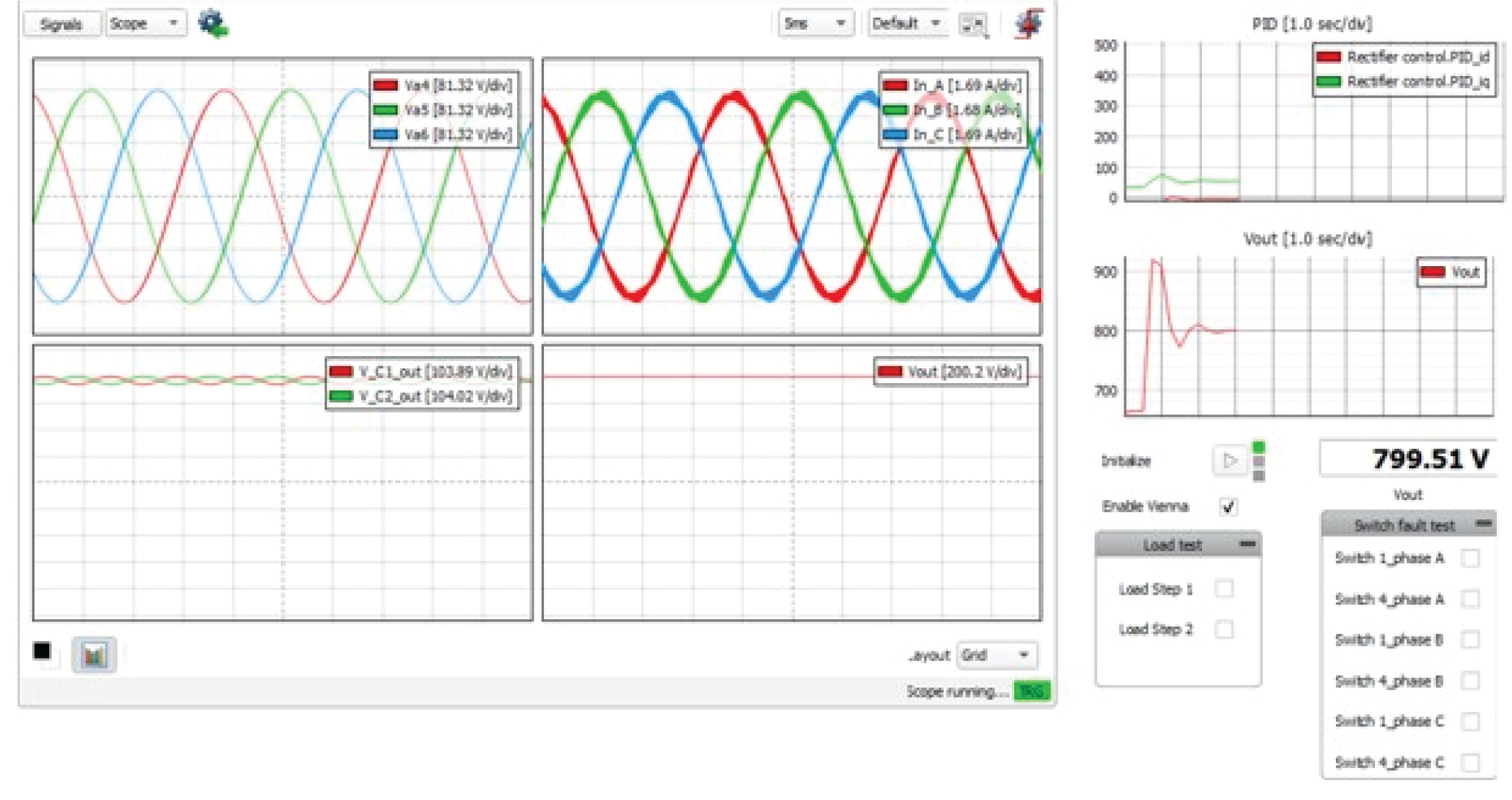
In our Application Notes, you can find a model of an NPC T Type Vienna rectifier to better understand how to implement the control system. Figure 3 shows what the SCADA would look like with the current and voltage waveforms. In addition, you could also include measurements of semiconductor losses and temperatures.
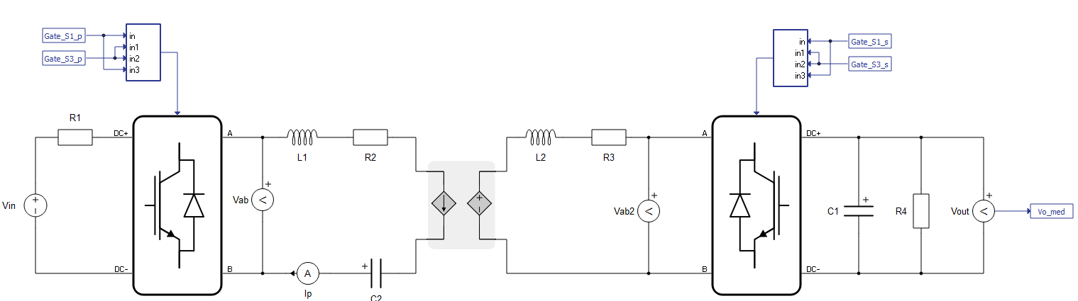
For the DC-DC stage, you could select the Dual-Active Bridge (DAB) converter, which can be built in the Schematic Editor using two blocks of single-phase inverters, the transformer, and the passive components, as shown in Figure 4.
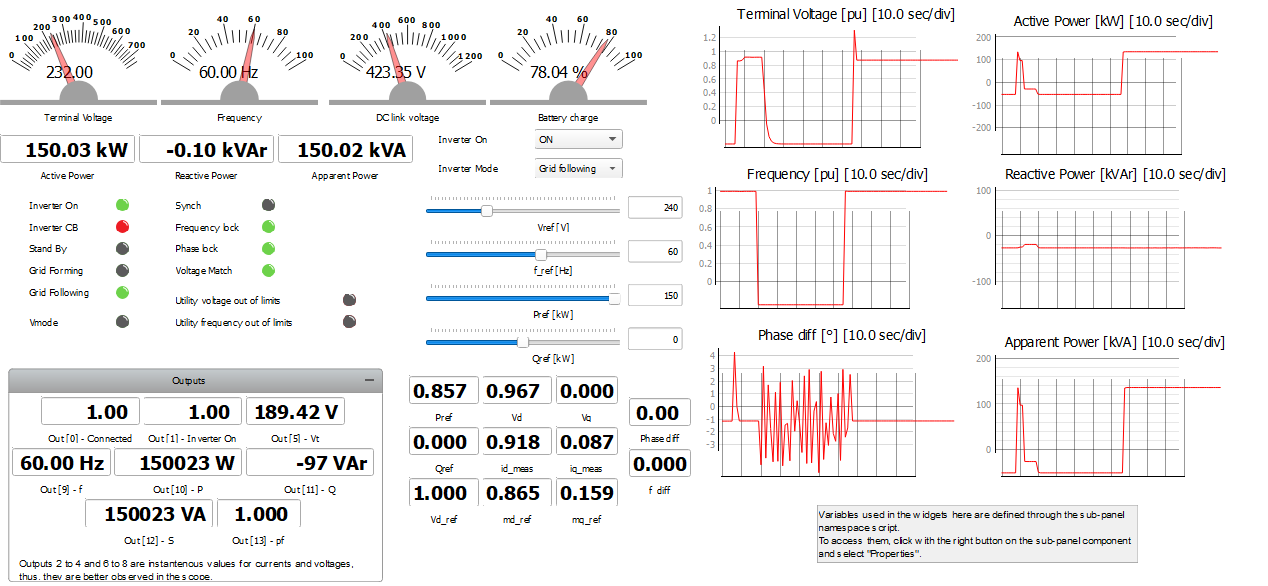
With HIL SCADA, you can manage, reconfigure, and monitor real-time simulations based on a customizable interface. It lets you control all functions of a DCFC station (status, mode, voltage, frequency, and P-Q references) while connected to the grid in real time. A DC Fast Charging model example from our documentation that combines all the power stages — from the grid to the EV battery — is shown in Figure 5. This panel includes graphs for the voltage and frequency of the grid, power exchange, and synchronization status.
You can further speed up the development of your DC fast charger by taking advantage of test automation features from our TyphoonTest and producing meaningful graphical reports using our integration with the Allure Framework. On top of that, our solution enables continuous testing with cloud integration for DCFC software and creates a simplified workflow for e-Mobility teams through integration with project management tools.
The bottom line is that e-Mobility is moving fast. Hence, automakers need to stick to continuous improvement cycles to keep up with new EV trends by reducing costs to remain competitive in the market. Testing and validating controllers throughout the DCFC development is vital to ensure an efficient and reliable charging process. Our HIL solution enables fast charger manufacturers to rapidly deploy software, reduce time-to-market, and overcome budget limitations with an all-in-one toolchain.
Credits
Text | Cassiano F. Moraes, Heitor J. Tessaro
Visuals | Hero image adapted by Karl Mickei, Figure 1 adapted by Milica Obradovic
Editor | Debora Santo